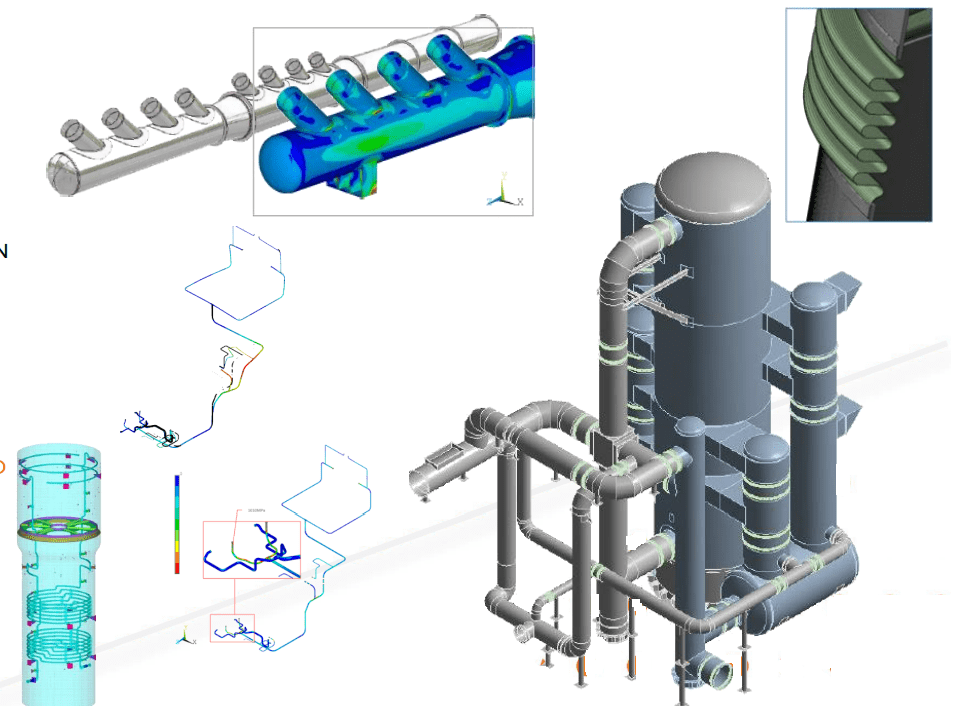
On certain occasions, during the development of projects where large diameter pipes are involved, scenarios arise in which the diameter (D) / thickness (t) ratio is higher than 100.
It is common to find this situation in systems with large diameter pipes that work at low pressure, in which the calculated thickness due to the internal pressure is very low.
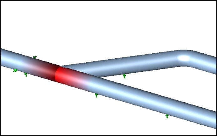
At the time of calculating the stress and flexibility of these pipes, special attention must be paid to the application of the Stress Intensification Factors (SIF). Thus, when looking at the ASME B31.3 code, in section 319.3.6 Flexibility and Stress Intensification Factors, it is indicated that, in the absence of more directly applicable data, the SIF should be consulted in Table 300 of Appendix D. It is in this part of the code that by a general note it is alerted that these values have only been validated for the situation where D / t <100 is true and therefore cannot be applied when D / t> 100.
In this case, the code in its latest editions refers to the ASME B31.J standard for its correct determination, although it is true that there are other methods to obtain them by using different tools.
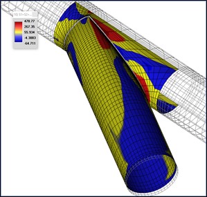
Once the SIFs have been properly determined, it is time to apply them in the stress and flexibility calculation. Usually, the most widespread calculation software directly applies these values based on Appendix D of the ASME B31.3 / 1 code if the D / t ratio <100. If, on the other hand, the D / t ratio is greater than 100, the software usually shows an «alert», but they allow the execution of the calculation and the obtaining of results, although not being valid. Therefore, the person using the software, as responsible for the calculation, must act appropriately and be aware.

In addition to the correct determination of the SIF and its proper application, it is necessary to emphasize that, in a pipe system in with great thickness, other phenomena that are not analyzed by the usual stress calculation software may appear. This is due to the fact that they are localized effects, caused by imperfections in the manufacturing process, non-uniform corrosion, pitting, and so on. Buckling, among others, is one of the phenomena that can appear; again the person responsible for the calculations must act appropriately and accordingly. At this point, it is not surprising that the system has to be validated by more advanced tools that can consider these phenomena and thus adequately evaluate the system against other types of failures. Finite Element Analysis (FEA) may be the solution for these cases.
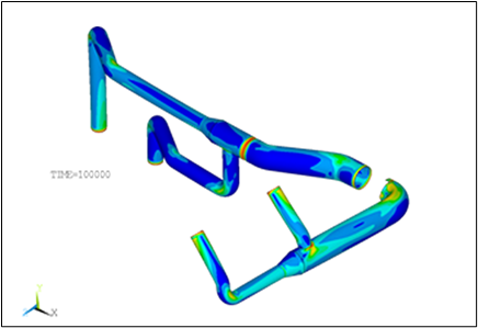
In conclusion, when starting the analysis of a large diameter and low thickness piping system, it is necessary to take into account calculation variables and mechanical phenomena that are not usually present in the most common piping systems of the facilities (diameters between 2 ” and 24 ”with thicknesses calculated for medium and high internal pressures). A proper problem approach, based on the design codes and with the use of the appropriate tools, will be necessary to ensure correct system design
Further information
For any query or request for additional information about our services and technologies, please complete the following form:

