STRESS ANALYSIS OF PIPES WITH RATIO D / t> 100

On certain occasions, during the development of projects where large diameter pipes are involved, scenarios arise in which the diameter (D) / thickness (t) ratio is higher than 100.

It is common to find this situation in systems with large diameter pipes that work at low pressure, in which the calculated thickness due to the internal pressure is very low.

Diversion in over-tensioned large diameter and low thickness pipe (CAESARII Software)

At the time of calculating the stress and flexibility of these pipes, special attention must be paid to the application of the Stress Intensification Factors (SIF). Thus, when looking at the ASME B31.3 code, in section 319.3.6 Flexibility and Stress Intensification Factors, it is indicated  that, in the absence of more directly applicable data, the SIF should be consulted in Table 300 of Appendix D. It is in this part of the code that by a general note it is alerted that these values have only been validated for the situation where D / t <100 is true and therefore cannot be applied when D / t> 100.

In this case, the code in its latest editions refers to the ASME B31.J standard for its correct determination, although it is true that there are other methods to obtain them by using different tools.

FEA analysis of a large diameter diversion (NozzelPRO Software)

Once the SIFs have been properly determined, it is time to apply them in the stress and flexibility calculation. Usually, the most widespread calculation software directly applies these values ​​based on Appendix D of the ASME B31.3 / 1 code if the D / t ratio <100. If, on the other hand, the D / t ratio is greater than 100, the software usually shows an «alert», but they allow the execution of the calculation and the obtaining of results, although not being valid. Therefore, the person using the software, as responsible for the calculation, must act appropriately and be aware.

Alert message (Software CAESAR II)

In addition to the correct determination of the SIF and its proper application, it is necessary to emphasize that, in a pipe system in with great thickness, other phenomena that are not analyzed by the usual stress calculation software may appear. This  is due to the fact that they are localized effects, caused by imperfections in the manufacturing process, non-uniform corrosion, pitting, and so on. Buckling, among others, is one of the phenomena that can appear; again the person responsible for the calculations must act appropriately and accordingly. At this point, it is not surprising that the system has to be validated by more advanced tools that can consider these phenomena and thus adequately evaluate the system against other types of failures. Finite Element Analysis (FEA) may be the solution for these cases.

FEA Analysis of a large diameter pipe system (ANSYS Software)

In conclusion, when starting the analysis of a large diameter and low thickness piping system, it is necessary to take into account calculation variables and mechanical phenomena that are not usually present in the most common piping systems of the facilities (diameters between 2 ” and 24 ”with thicknesses calculated for medium and high internal pressures). A proper problem approach, based on the design codes and with the use of the appropriate tools, will be necessary to ensure correct system design

Further information

For any query or request for additional information about our services and technologies, please complete the following form:

Looking forward. Advanced Mechanical Solutions

Looking forward. Advanced Mechanical Solutions

CADE initiated last October 25 the 5th edition of its course about ANSYS WORKBENCH in Albacete School of Industrial Engineering, frameworked within the collaboration that CADE maintains with University of Castilla-La Mancha (UCLM). CADE initiated last October 25 the 5th edition of its course about ANSYS WORKBENCH in Albacete School of Industrial Engineering, frameworked within the […]

CADE: lecturer at Seminar of Energy – CIEMAT

CADE: lecturer at Seminar of Energy – CIEMAT

CADE will be present as a lecturer on the 2nd Edition of the Energy Seminar that will be held next February 23rd 2016 at CIEMAT headquarters. The event, hosts by ANSYS and CIEMAT, seeks the goal of being a meeting place for the energy sector with testimonies of clients, and focused on ANSYS Version 17.0 […]

CADE imparte un curso de introducción al FEA en la UCLM

CADE imparte un curso de introducción al FEA en la UCLM

(Español) CADE impartirá el próximo 10 de abril de 2013 un seminario informativo enfocado a los docentes, en el cual se plantean las capacidades del análisis y simulación mediante el empleo de uno de los software de simulación por elementos finitos punteros en el mundo ANSYS WORKBENCH.

Estudio de la influencia de la triaxialidad en la aparición de grietas y evolución de la fractura en soldaduras

Estudio de la influencia de la triaxialidad en la aparición de grietas y evolución de la fractura en soldaduras

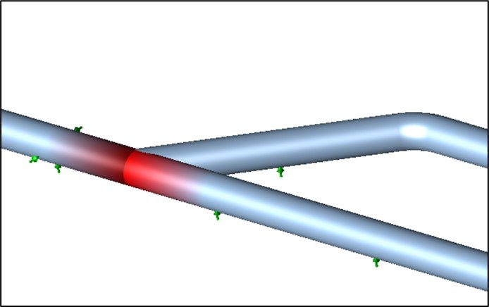
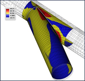
(Español) CADE aplica esta metodología para el análisis de soldaduras como herramienta para la detección de fallo en servicio o en las fases previas de diseño en aquellas soldaduras que por su gran tamaño no pueden ser evaluadas con métodos tradicionales.

Estandarización de modelos FEM a partir de modelos parametrizados APDL

Estandarización de modelos FEM a partir de modelos parametrizados APDL

El compromiso de CADE con nuestros clientes siempre nos lleva a buscar la reducción del tiempo de análisis y modelado 3D en la validación y optimización de equipos y estructuras de proceso con Análisis de Elementos Finitos. Una herramienta útil para trabajar en este propósito es la construcción de modelos parametrizados en ANSYS Mechanical APDL […]

FEM models standardization from APDL parameterized models

FEM models standardization from APDL parameterized models

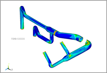
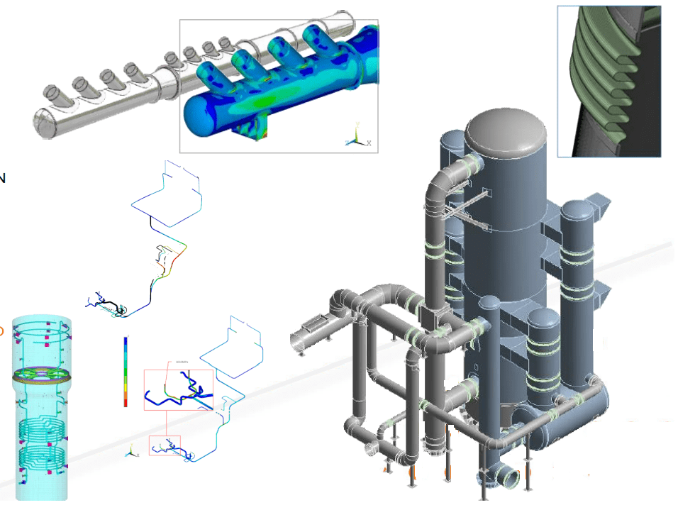
CADE’s commitment with our customers always lead us to look for 3D modeling and analysis time reduction in validation and optimization of process equipment and structures with Finite Element Analysis. One handful tool to work on this purpose is the construction of Parameterized models in ANSYS Mechanical APDL and ANSYS Workbench. One of the most […]

1 2 3 4